Friday, May 8, 2015

Railings - Instance Modifications

Railings - Instance Modification


The previous post was intended to familiarize you modifying railings and handrail types at the Type level.  In this post, we will go through how to modify railing components at the instance level.  

  • Hover over the railing of which you wish to make instanced based edits.  For this example, we will look at duplicating a support bracket on a wall mounted handrail.  Refer to Fig-1 for an elevation view of a wall mounted handrail with standard spacing as driven by our Handrail Type, prior to instance based editing.
Fig-1:  Elevation View Type Driven Support Spacing

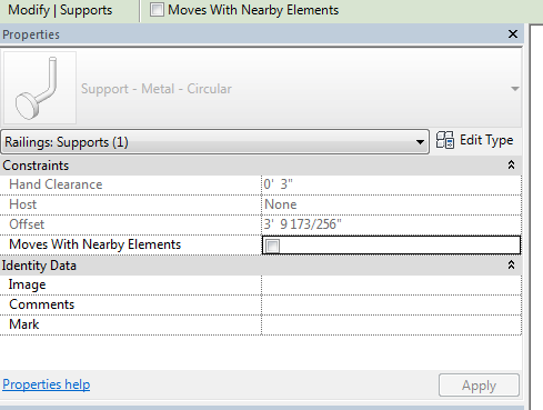
  • While hovering over the Railing Type, hit Tab to cycle through your selection options until you can select only the support bracket closest to the bottom of the stair run.  The support bracket will be selected and a pin icon will appear (Fig-2).  This is telling us that the position of this support bracket is driven by the Type Properties of the Handrail Type.  Also note that the properties of the support bracket, including the preview image, are grayed out (Fig-3).
Fig-2:  Support Bracket Selected

Fig-3:  Support Bracket Pinned
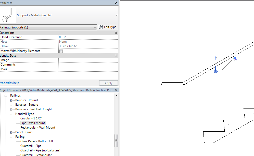
  • If we wish to move the bracket or modify the support depth, click on the pin to allow instance based editing.  This will change the pin graphics to open as well as remove the grayed out tone from the Properties dialog box.
Fig-4:  Support Bracket Unpinned
  • Once the support is unpinned, you are now able to edit the individual support on an instance basis.  Changes made to this support, be-it location, hand clearance, etc. will only apply to this one support bracket.  Brackets can be moved by entering a horizontal distance and the support will automatically move to remain attached to the rail.  If you move a support by mistake, clicking the pin will return the object to its original Type driven location.
  • If you wish to copy a support, you do not need to unpin the original object.  Simply use your copy command and add a bracket at the desired location.  The newly copied support will be automatically unpinned because it not driven by the Type Properties of the Handrail Type (Fig-5).
Fig-5:  Copied Support vs Type Driven Support

  • It is important to note that only Continuous Rails, top rails as defined by a Top Rail Type and handrails as defined by a Handrail Type, and their sub-elements, supports and terminations, can edited on an instance level.  Non-Continuous rails do not offer this ability.
  • To edit that handrail itself, hover over the Railing Type and hit "Tab" until the handrail only is selected. Once selected, the new panel will appear in the Ribbon, labeled "Continuous Rail" (Fig-6).  By clicking on the Edit Rail button, we will be able to edit the handrail at the instance level.
Fig-7:  Continuous Rail Panel
  • Within the edit rail command, we are able to edit the profile as well as the path of the railing, by clicking on the Edit Path button (Fig-8).
Fig-8:  Edit Path
  • In addition to being able to edit the path of the rail from this dialog box, we also are given the option of editing the rail joins.  Once clicked, we will snap only to intersections of rail segments.  Once selected, the adjacent combo box will become activated and we can modify the join from by type to either Miter or Fillet.  If we chose fillet, we must specify a radius for the join.  A miter and fillet join are indicated below in Fig-9.1 and 9.2.
Fig-9.1:  Mitered Rail Joint
Fig-9.2:  Fillet Rail Joint


  • Once you are happy with your edits, click the green check mark twice to complete your edits.
  • Feel free to experiment with your railing edits on an instance level.  You always have the ability to go back to the Type driven properties by selecting the Railing Type and hitting the Reset Railing button (Fig-10).
Fig-10:  Reset Railing

Creating Railings

Creating Railings


The previous post was intended to familiarize you with the structure of the railing tool.  In this post, we will go through how to modify existing railings to create new railings specific for your projects.  

Please note that Amenta|Emma Standard guardrail/railing designs are pre-loaded into the large template file.  These standard model elements correspond with our standard railing details and should be used for egress stairs.

Decorative stairs will often necessitate the need for custom stairs and railings.  The following is an overview of how to modify rail structures and other components.  For complicated decorative stairs, please consult your project BIM Coordinator and/or the BIM Manager for assistance/recommendations.
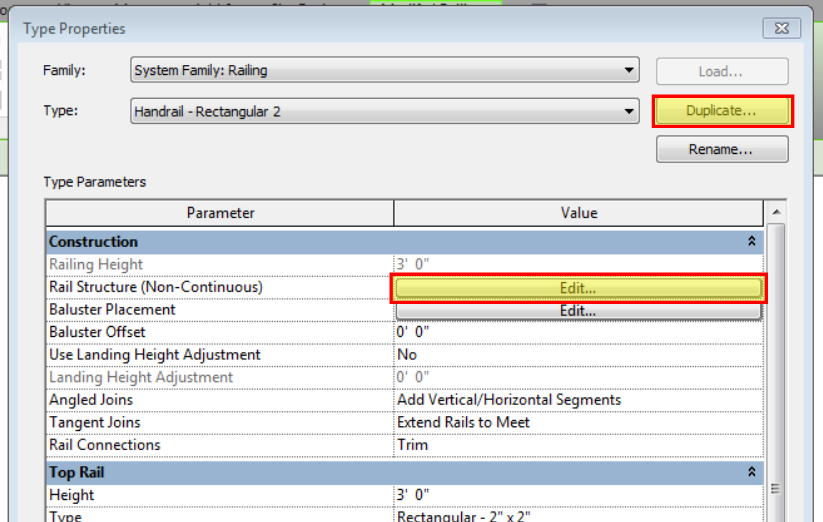
  • Select the railing you wish to duplicate and click the Edit Type (Fig-1) and select Duplicate (Fig-2).  This will prompt a Name box - enter the name for your new railing and hit ok.
Fig-1:  Select Edit Type
  • Click on the Edit button next to the Rail Structure (Non-Continuous) to edit horizontal railing members, other than the handrail and top rail components (Fig-2).  These will be edited using the Top Rail and Handrail Types.  
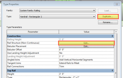
Fig-2:  Duplicating Railings and Editing Non-Continuous Rail Structure
  • Once inside the Edit Rails (Non-Continuous), insert horizontal railings as per your design intent, using the Insert Button (Fig-3).
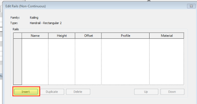
Fig-3:  Insert Non-Continuous Horizontal Rails
  • Once inserted the rail must be named, given a height and offset and a profile.  The material can be added at this point or later.  Profiles for the railing must be selected from a pull-down list of profiles loaded into the project, so any custom rails must be created before they will become available for selection (Fig-4).
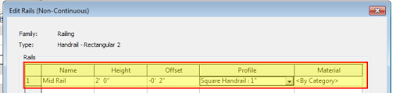
Fig-4:  Completed Non-Continuous Rail
  • Once you have created your first rail, you can duplicate the rail, and change the properties as necessary for your rail design.  After all non-continuous rails have been completed, use the OK button to save your updates and exit out of the Edit Rails dialog box.
Next, we will take a look at using the Continuous Rails, whether it be the Top Rail, Handrail 1 or Handrail 2.  Each of these continuous rails are driven by Handrail and Top Rail Types.  These can be found within the family browser under the Railing Heading (Fig-5).
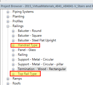
Fig-5:  Handrail and Top Rail Types in Family Browser
  • When expanded, all handrail/top rail types currently in the project will be visible.  These handrail/top rails are then able to be loaded into the Railing System Family.  To edit a handrail/top rail type, double-click on the type you wish to edit and the corresponding type properties dialog box will appear (Fig-6).
Fig-6:  Handrail Type  Type Properties Dialog
  • Edits done within this dialog box will change all locations in which this handrail type is assigned (unless they have been edited on a instance base) - handrail types can be assigned to multiple railing types.  Individual handrail types can also be editing on an instance level once they are loaded into a railing type by "tabbing" the railing type until the handrail type is selected.
    • One item to note is that there is a bug in Revit related to the Support Family.  if you change the support type and hit ok, nothing will happen to the model elements.  To make the changes execute, you must make a change to the position of the handrail type within the railing type it is loaded into.  This will update the support family, but likely put the support on the wrong side of the railing.  Change the side back after the model support has been updated.
  • Once you have finished editing your handrail types, it is time to assign them to your railing type.  This is achieved through the Type Properties of the Railing System Family.  
    • Select the model representing the railing you wish to modify and hit edit type.  This will bring us back to the Type Properties of the Railing System.
    • Find the continuous rail you wish to assign, Top Rail for a top or guardrail and either Handrail 1 or Handrail 2 for a handrail element.
    • Once you have found the correct rail, use the pull-down under type to select your crated handrail type.  Once changed, the lateral offset and height will be filled in, but grayed out.  These are grayed out because their values are driven by the type properties of the handrail type.  A position option becomes available to select where the handrail type will be placed relative to the Railing Type host, see Fig-7.
Fig-7:  Assigning Handrail Type to Railing Type
    • Once you have assigned your handrail type, click OK and all Railing Types will be updated with your new handrail type.  See Fig-8.
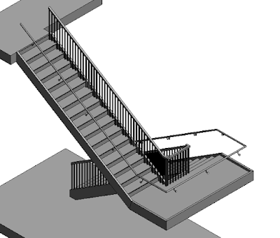
Fig-8:  Updated Railing with Handrail Type

As mentioned above, handrail types as well as supports, can be edited on an instance basis, and allow fine-tuning of specific conditions. 

This will be covered in the next post, "Railings Instance Level".

Railing Overview

Railing Overview


As a follow-up to our recent in-house lunch and learn, the below is meant to document the items reviewed and be a future reference.

An overview of the components/organization of railings.
  • Railings are comprised of both continuous and non-continuous horizontal members, vertical balusters, supports and terminations.  The newer system families are the top rail and handrails (see Fig-1 below) and the new user created families are supports and terminations.
Fig-1:  Railing Type Properties Dialog Box
  • It is important to note, that there is no family template for the user created supports or terminations.  To create a new support or termination family, the recommended practice is to start with a generic model family (unhosted) and change the family category (Fig-2) to support or termination (Fig-3).
Fig-2:  Family Category
Fig-3:  Railing Categories
A graphical representation for the Railing Typology is included below (See Fig-4).

Fig-4:  Railing Typology
For information on creating/modifying railings, see the next post "Creating Railings"

Tuesday, February 24, 2015

Using the View Reference Tool

Using the View Reference Tool


It is very common for us to type view references into notes during the construction document process.  However, if the view that you are referencing is relocated, the text must be manually updated to reflect the new drawing location.  With a large project containing hundreds of sheets and views, back-checking this can be a very time consuming process.

To eliminate the need to back-check typed references, we can substitute the typed reference for a "smart" VIEW REFERENCE" which will link to a view the same way in which a section or other tag would.

Let's walk through how to place a view reference.

  • Type your text note as you normally would.  When you get to the location you would manually type the reference, use leave a space of about 10 characters as a placeholder for where the view reference will be placed.  The exact space will need to be verified with the reference after placed.
  • Browse to the View Tab of the ribbon, and select the View Reference option under Sheet Composition

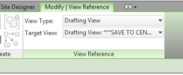
  • Once the View Reference command has been selected, a View Reference specific toolbar will appear in your ribbon.  Two pull-downs will appear, one for view type (Drafting View, Elevation, Detail, etc.) and a second for the Target View (the actual view name you want to reference.)

  • Select the type of view you want to reference from the View Type pulldown and then the specific view that you want to reference from the Target View pulldown.  After the view has been selected, click once to place the view reference within the open space left inside the text note.

COMPLETED NOTE WITH VIEW REFERENCE PLACED
  • With the View Reference placed, you now have a smart tag that will update if the target view is ever moved.  Additionally, double-clicking on the view reference will take you directly to the target view.

One thing to note:  The view reference in our current template is not correct.  It will be loaded into the new 2015 template once it is completed.  In the interim, if you want to use this command (highly recommended), you can load it from the library under annotations (select overwrite and parameter values).  When placing, use the 3/32" option for placement within typical notes.  Once loaded, it will automatically become an option under view reference


Wednesday, July 30, 2014

Extending Individual Wall Layers

Extending Individual Wall Layers


It is often the case that various layers of walls will need to extend to different heights.  For example, you may have an interior wall where the framing needs to extend to the underside of the deck, but the gypsum board can stop 4-6" above the ceiling.  This could be handled in a detail view via 2D linework (cut profile), but the more effective way is to modify the height of individual layers of the wall.  This is particularly effective for large projects where clash detection is going to be used to avoid unnecessary conflicts and where the model will be used for estimating quantities of materials.

  • Here is our wall section:


  • Click the 'Edit Type' option and then click on the 'Edit' button under structure.  This will bring us to the 'Edit Assembly' window where we can see the layers of our wall.
  • By default, all of the layers of your wall assembly will start and stop at the same height.  If we wanted individual layers to be capable of extending higher than others, we need to enable the extension parameter for this wall type.
    • Step 1:  Edit the Wall Type:

    • Step 2:  Edit the structure (for this type):

    • Step 3:  Enable the preview of the wall assembly:

    • Step 4:  Change the preview view type to Section:

    • Step 5:  Click the Modify button under Modify Vertical Structure.

    • Step 6:  Click on the top or bottom of the layer you wish to extend/trim.  You should see a lock appear.  Click on the lock to 'unlock' the layer.  Repeat for as many layers as you wish to unlock.  Once complete, click OK a few times until you are out of the edit type dialog box.
  • Once you have completed the unlocking of the wall layers, we can return to the model and edit the walls where we need to.  There are two ways to modify the heights of unlocked layers, either by entering a top/base extension distance:
Note the Top/Base Extension Distance Options are no longer grayed out.

  • or by dragging the layer (via grips) to the correct height (6" above the ceiling in the example below):
Note the two different grips for the top of wall height


Friday, June 6, 2014

Changing a Room's Level

Changing a Room's Level


It is often the case that Rooms within Revit are inadvertently created on the incorrect level for a multi-story building.  Depending on the stage of the project when this is noticed, simply deleting the room and recreating it could cause the loss of all data associated with the room (finishes, occupancy, department, etc.) since Revit does not allow you to simply change the level of the room from the properties panel.  This was recently encountered on the Housatonic project, when a schedule was generated that filtered rooms by level for the addition portion of the project.  The following is a step-by-step process of how to the level of these rooms were revised without loosing the associated data:


  • The below is a screen shot of the properties of the room prior to changing the room level for reference.  As you can see this room has finishes, an occupancy, a department and an occupant load associated with it, all which we want to retain after switching the level to the correct level.
  • Go into a floor plan and hover/tab until you select the room (the blue X in the image above) and delete the room.  Be sure to delete the Room and not the Room Tag.  
  • When you delete the room, you will get an error message stating that the Room has been deleted from the view but still exists in the project (see below).  This is the correct message you want to see.  You can ignore this warning as we are going to eliminate the warning with the corrective measures outlines below.

  • Go back to the same floor plan and enter the Room Command to place a Room.  When you enter the command you will see a green toolbar appear below your ribbon.  The first and most important step is to ensure you select the correct level for the room. This can be selected from the properties bar under upper limit.  Prior to clicking in the room location, use the pull-down Room: New (in the image below) and select the room you previously deleted.  Note: this pull-down will give you a list of all unplaced rooms in your model.  This is good opportunity to look at which rooms can be deleted from your project to help control file size.


Select the Room you wish to re-place
  • Place the "new" room into the original location and check your properties to see that all of the attached information is still associated with the room.

  • One thing to note:  You will need to re-tag the room in your other plan views.  This only replaces the Room and not all of the tags.

Monday, April 14, 2014

Save to Central Best Practices

Save to Central Best Practices


The following is a list of best practices for synchronizing with central (SWC) in Revit:

Never leave for extended periods of time (Lunch, Meeting, Home, etc.) immediately after hitting the Sync button.

  • Revit will often ask for user input before the process is complete.  If this happens while you have left, your team can be stuck with a central file that is in use and would not allow them to save and/or keep working.
Use the Worksharing Monitor (WSM) and consult it before hitting the Sync button.


  • Knowing if someone else on your team is currently saving, can save you time with your own save to central as only one save request can be completed at a time.  If someone else is saving  to central and you attempt a save, you will receive an error message indicating that central file is busy and you will have to wait until both saves are completed to continue working.  Wait for an opening in the WSM and then sync.
  • The worksharing monitor for Revit 2014 can be found in the Autodesk folder on the S drive.

Sample screen shot from the WSM


Always use the Sync and Modify Settings Command.

  • This ensures that you are presented with the dialogue to release borrowed and owned elements, to ensure others on your team are able to access them.
  • Check all available boxes when syncing (with the exception of the Compact box), so that all objects and elements are returned to the central file.


  • Add comments in the field provided.  These comments are helpful in tracking down problems that may occur from time-to-time in the model.  Short, concise descriptions of work are all that is required.  This is a problem solving tool for project BIM Coordinators.
  • Always save locally when prompted.  SWC when prompted when working alone, or after consulting the WSM on a small project team (2-5 users).  For projects with more users, consult with your project's BIM Coordinator.  When more than 5 users are working on a project, there is typically a SWC schedule to follow to minimize time spent in queue.
  • Over-communication with your team is better than poor communication.  Make sure you and your team are all on the same page.