Showing posts with label #REVIT. Show all posts

Monday, February 1, 2016

Understanding PAT Files

Understanding PAT Files


Filled regions are used on every Revit project that we do.  While our library has a large number of standard materials created as filled regions, a specific design may require a new filled region to be created.

Complex filled regions are created using PAT files.  If you are not familiar with PAT files, at first glance they can be somewhat confusing.  The below is a summary of what each number in the pat file means, so you can be better equipped to create your own custom PAT files for your projects.  

First, the default Revit .pat file is located here:  C:\Program Files\Autodesk\Revit Architecture 2016\Data.  When making new patterns files, I often find the best way to do it is to start a new notepad file for your specific filled region.  If you think your filled region should be incorporated into the office template file, please e-mail it to me and I will take a look and include in the next template update.

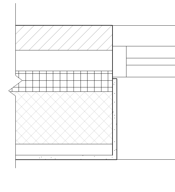
Here in an example of a new .pat file that was created for a project in the office last week, for a 24 x 36 cork wall tile, in a running bond pattern.

And now for the notepad file that was used to create this pattern.

*Cork Tile 36x24, 36 x 24 Tiles Stagger
;%TYPE=MODEL
0,     0,     0,      0,      24
90,   0,     0,     24,     18,     24,     -24

The first row of numbers creates the horizontal lines for the pattern:
Angle            = 0         -->  lines are horizontal
x,y origin       = 0, 0    -->   defines the starting point of the lines
shift               = 0        -->  line pattern is not shifted
offset            = 0         -->  consecutive lines are 24 inches apart
no line pattern            -->  the line is solid

The second row of numbers creates the vertical lines for the pattern:
Angle            = 90      -->  lines are vertical
x,y origin       = 0, 0    -->  pattern begins at the same point as the horizontals
shift               = 24      -->  line pattern is shifted by 24 model units for consecutive lines
offset            = 18       -->  consecutive lines are 18 inches apart
dash             = 24       -->  each line is built of 24" dashes and 24" spaces
space           =24        -->  this pattern repeats until the face boundary


Friday, June 5, 2015

QUICK TIP - COMPONENT PLACEMENT

Quick Tip - Component Drop Down


Searching for a family to place into your model or detail that is loaded into the project and you don't want to scroll through the entire list or use the browser on the bottom left?

In 2015, you are in luck!  You can now search the component drop down list by typing the name of the family, or the specification number if you are using the new family naming conventions.

Looking for a CMU detail component?  Simply start to type 04 and the list is filtered with your search criteria highlighted in yellow.

Wednesday, May 20, 2015

Snap Override

Quick Tip - Snap Override


Whether you are sketching the outline of a model element (roof, floor, etc.) or trying to draw a detail line, it is inevitable that at some point you will encounter a situation where Revit does not let you draw the line at the angle you want (typically less than 2 degrees).  This can become very frustrating for many users.


Luckily, if you remember your days in AutoCAD (I know, I used the word AutoCAD in a Revit post), you can use a tool very similar to manual snap override in Revit and it is SIMPLE to  use.  Simply follow these steps:


  • Sketch your line as you normally would.
  • When you are unable to connect your line as you want to, Right Click in your space and click on the Snap Override text.  This will bring up a list of available snaps that you can select from (See Fig-1 below).  Click the snap you want and now you will only select that type of snap.

Fig-1:  Snap Overrides

This can also save you time if you are used to using your "TAB" key to cycle through all of your snap options.  Now, you can isolate the type of snap you are looking for.


Friday, May 8, 2015

Railing Overview

Railing Overview


As a follow-up to our recent in-house lunch and learn, the below is meant to document the items reviewed and be a future reference.

An overview of the components/organization of railings.
  • Railings are comprised of both continuous and non-continuous horizontal members, vertical balusters, supports and terminations.  The newer system families are the top rail and handrails (see Fig-1 below) and the new user created families are supports and terminations.
Fig-1:  Railing Type Properties Dialog Box
  • It is important to note, that there is no family template for the user created supports or terminations.  To create a new support or termination family, the recommended practice is to start with a generic model family (unhosted) and change the family category (Fig-2) to support or termination (Fig-3).
Fig-2:  Family Category
Fig-3:  Railing Categories
A graphical representation for the Railing Typology is included below (See Fig-4).

Fig-4:  Railing Typology
For information on creating/modifying railings, see the next post "Creating Railings"

Wednesday, July 30, 2014

Extending Individual Wall Layers

Extending Individual Wall Layers


It is often the case that various layers of walls will need to extend to different heights.  For example, you may have an interior wall where the framing needs to extend to the underside of the deck, but the gypsum board can stop 4-6" above the ceiling.  This could be handled in a detail view via 2D linework (cut profile), but the more effective way is to modify the height of individual layers of the wall.  This is particularly effective for large projects where clash detection is going to be used to avoid unnecessary conflicts and where the model will be used for estimating quantities of materials.

  • Here is our wall section:


  • Click the 'Edit Type' option and then click on the 'Edit' button under structure.  This will bring us to the 'Edit Assembly' window where we can see the layers of our wall.
  • By default, all of the layers of your wall assembly will start and stop at the same height.  If we wanted individual layers to be capable of extending higher than others, we need to enable the extension parameter for this wall type.
    • Step 1:  Edit the Wall Type:

    • Step 2:  Edit the structure (for this type):

    • Step 3:  Enable the preview of the wall assembly:

    • Step 4:  Change the preview view type to Section:

    • Step 5:  Click the Modify button under Modify Vertical Structure.

    • Step 6:  Click on the top or bottom of the layer you wish to extend/trim.  You should see a lock appear.  Click on the lock to 'unlock' the layer.  Repeat for as many layers as you wish to unlock.  Once complete, click OK a few times until you are out of the edit type dialog box.
  • Once you have completed the unlocking of the wall layers, we can return to the model and edit the walls where we need to.  There are two ways to modify the heights of unlocked layers, either by entering a top/base extension distance:
Note the Top/Base Extension Distance Options are no longer grayed out.

  • or by dragging the layer (via grips) to the correct height (6" above the ceiling in the example below):
Note the two different grips for the top of wall height


Monday, April 14, 2014

Save to Central Best Practices

Save to Central Best Practices


The following is a list of best practices for synchronizing with central (SWC) in Revit:

Never leave for extended periods of time (Lunch, Meeting, Home, etc.) immediately after hitting the Sync button.

  • Revit will often ask for user input before the process is complete.  If this happens while you have left, your team can be stuck with a central file that is in use and would not allow them to save and/or keep working.
Use the Worksharing Monitor (WSM) and consult it before hitting the Sync button.


  • Knowing if someone else on your team is currently saving, can save you time with your own save to central as only one save request can be completed at a time.  If someone else is saving  to central and you attempt a save, you will receive an error message indicating that central file is busy and you will have to wait until both saves are completed to continue working.  Wait for an opening in the WSM and then sync.
  • The worksharing monitor for Revit 2014 can be found in the Autodesk folder on the S drive.

Sample screen shot from the WSM


Always use the Sync and Modify Settings Command.

  • This ensures that you are presented with the dialogue to release borrowed and owned elements, to ensure others on your team are able to access them.
  • Check all available boxes when syncing (with the exception of the Compact box), so that all objects and elements are returned to the central file.


  • Add comments in the field provided.  These comments are helpful in tracking down problems that may occur from time-to-time in the model.  Short, concise descriptions of work are all that is required.  This is a problem solving tool for project BIM Coordinators.
  • Always save locally when prompted.  SWC when prompted when working alone, or after consulting the WSM on a small project team (2-5 users).  For projects with more users, consult with your project's BIM Coordinator.  When more than 5 users are working on a project, there is typically a SWC schedule to follow to minimize time spent in queue.
  • Over-communication with your team is better than poor communication.  Make sure you and your team are all on the same page.


Monday, March 17, 2014

View Templates

View Templates


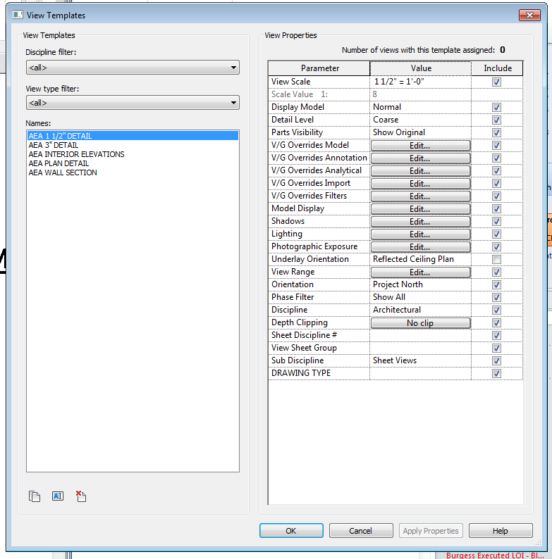
As indicated in other posts (Lean Design with REVIT), sheets and views should be set up as early as possible, utilizing standard AEA view templates.  A series of standard view templates have been created and preloaded into our office template files.  These viewports cover the most common drawing types, other than plan views.  See below for a list of standard View Templates:


Since each project varies on the exact view templates required, additional view templates will need to be created by the project BIM Coordinator, including plan views.  Also, the standard view templates may need to be modified on a project by project basis, depending on your project.  For example, if you have linked consultant files, the view templates will need to be updated to control how these model display in our views.  Review with your project BIM Coordinator, or a member of the BIM team for assistance.


Once the view templates are in your file, they must be assigned to your views.  The easiest and most efficient way to do this, is through your properties window.  Double click on the view that you wish to update from the project browser.  Once in the view you wish to apply a template too, scroll down to the identity data section of the properties window.


When a view does not have a view template assigned, the Identity will indicate <None> as seen in the above image.  To apply a view template, click on the none button.  This will bring you to the view template dialog box where you can select the appropriate view template to apply, clicking on the view template and clicking the apply button, then hitting OK the exit the view template window.  Once this is completed, the Identity Data field will be updated to the selected view template and your view will be updated accordingly.


Using View Templates will not only ensure a consistent appearance of drawings throughout your set and our office, but will save you time previously spent on hiding elements, adjusting lineweights, etc. on a view by view basis.

Standard Titleblock Update

Standard Titleblock Update


As part of our Quality of Documents Team ongoing efforts to improve workflows and user experience, we have updated our standard Revit titleblocks, with an update to the grid used for locating drawings on sheets.

In the past, the grids were turned on or off via a check box in the Properties of the titleblock within your Revit file, labeled "Display Detail Grid".


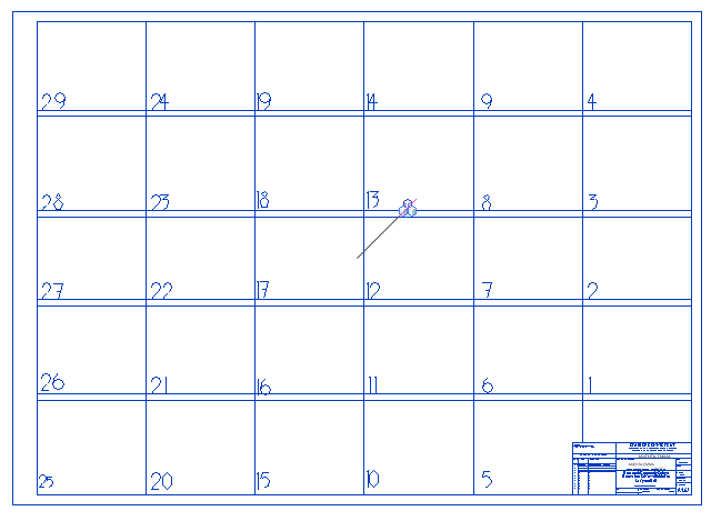
While this was an acceptable way to toggle these grids, since this option was sheet specific, it was often the case that the grids were left on one or several drawing sheets when a set of documents was printed.  In response to this, the standard titleblock has been updated to utilize a series of invisible lines that will never print and are visible on demand to the user for placing views.  Let's look at an example in action.  Below is a look at a standard titleblock for State of CT projects:


No grid-lines visible when not requested by user.

If the user wants to see the grid-lines to place a view, simply hover over the titleblock, and the grid-lines appear.


Since the grid-lines only appear when the user requests them, placing a view in the correct spot requires a different approach then previous titleblocks.  Use the following steps:
  • Drag the desired view onto the desired sheet.
  • Left click on the view once placed on the sheet.
  • Move your cursor and hover over the titleblock until the grid-lines are visible.
  • Use the arrow keys on your keyboard to shift the heading and view to the correct location on the sheet.

Lean Design with REVIT

Lean Design with Revit


A major issue that we constantly struggle with while working on projects is the file size of our models.  While this is mainly an issue on our larger projects, we can also benefit from a leaner file on small tenant projects.  The leaner the file, the less Revit has to process in the background, the faster the program responds to our commands.

Below are some tips on keeping your Revit file lean (note:  some of these tips can be found in our Quality of Documents Manual section 1.7)


  • Warnings:  Revit provides us with warnings to let us know that we are doing something incorrectly.  While these are commonly ignored due to time constraints or lack of knowledge on how to resolve, these warnings should not be ignored.  If left unchecked for too long, the Revit model can amass upwards of 700, 800, or even 1000 warnings. These warnings can make the Revit model slow and cumbersome, because it keeps looking to see if the warnings have been fixed. The most common and easiest to fix warnings are related to room separation lines overlapping each other or walls and warnings saying that two items have the same type mark which should be able to be corrected by any Revit team member.  More complicated warnings like ramp slope, stair riser warnings, unenclosed rooms, etc. may require the assistance of your project BIM Coordinator or a member of the BIM Team.  Reach out for assistance if you are unsure how to correct your warnings, but DO NOT IGNORE them.
  • Over complicated Elements:  While Revit is capable of modeling many complicated things and making them parametric, you most likely do not need to.  When in doubt, follow the famous KISS mantra, Keep It Simple Stupid.  In Revit, this would mean only model what you need, when you need it.  Also, be conscious of items that you download from Revit City or manufacturers, as these tend to be over complicated.  Remember the saying, you get what you pay for.  Since these elements are free, they are often not the ideal elements to bring into your project.  No elements downloaded from an outside source (Revit City, Autodesk Seek, etc.) should EVER be placed into your Revit model without review by the project's BIM coordinator.
  • Unused Views:  Revit is very powerful when it comes to creating different types of views. This is great, however, an excessive amount of views—especially 3D perspective or isometric views—can weigh a model down. Once you're done using the section you cut to quickly check something, make sure to delete it. Try keeping the philosophy of "name it or delete it" when it comes to views to keep your model in check as you go. 
  • Large or Complicated Sketch-Based Items:  This means roofs, floors, ceilings, filled regions, ramps, stairs and any other item that put you into pink lined sketch mode. Complicated sketches using a lot of splines require Revit to process more information. This doesn't mean we shouldn't design wild curvy ceilings, it just means we should keep an eye on how that ceiling is impacting the file. Consider modeling these items as families outside of the project.  Review with the BIM coordinator for advice / direction.
  • Unused Families:  Don't be a hoarder when it comes to Revit families in your model. Keeping a small collection of items you are sure you'll need in the future is ok, but keeping every piece of casework you loaded just in case you need it someday is not. If a component you need accidentally gets purged, it can always be loaded back in. 
  • Groups:  Groups always seem like a great idea at first, but they wind up functioning differently than you expect them to. Use groups sparingly and with good reason. If it seems like your group could be made into a static family, it probably should be. Also, be wary of the types of components you're grouping together. Wall hosted items like sinks or doors can have issues when they're grouped away from their host (the wall), or in with non-wall hosted items like sinks or casework. 
  • Embedded CAD Files or Images:  This is a huge source of file size and model performance problems in Revit. If you absolutely must bring CAD into a Revit model, always save a copy of the file first and clean out the riff raff. Delete any elements that somehow snuck off into no man's land, purge the file, run the "overkill" command and audit it. Make sure when you type in "Z E" for zoom extents that your drawing is centered on the screen.  
    • When you bring the CAD in, always link it instead of embedding it. That way, you can find the file when you need to modify it, reload it or remove it. Embedded CAD has the knack of getting lost in your views. Sometimes it can get hidden and become difficult to find. CAD files found to be embedded and not linked are subject to deletion by the BIM coordinator at any time.
  • In-Place Families and Overloaded Hosts:  These should be used very sparingly, if at all. Modeling in an outside family is actually easier than using the family editor. Also, when you copy an in-place family, it makes another family. Before you know it you could have Special Casework 1 ,2, 3, ... 25.... Only use an in-place family if it's something you can't model outside of the project in the family editor. 
  • Lengthy List of Design Options:  Once you are done using a design option, delete it. When there are a large amount of design options in the model, Revit has to think about how each option influences the objects around it. The more you have, the more thinking that occurs and the slower your model. 
  • View Detail:  Do you have a lot of views that are using fine or medium detail level but have scales like 1/16", 1/8"=1'-0"? These views won't really show this level of detail for all elements effectively and you are asking the computer to show it anyway. 
  • Saving to Central Using the Project Information Screen:  This is a simple legend view (previously presented) that will help your model open faster. Synchronizing with a 3D view open, especially one that has shadows on, will take a long time to open next time you want to access the file. Revit has a tool under the manage tab that allows you to designate which view you want Revit to open the file with. Your Open Save Page or another small view should be selected for this task).
  • Auditing (Once or Twice a Week):  Checking this box will give you a warning that it will take a long time. However, I've never seen it take much longer than the usual load time. If you are ever having issues with your file crashing or behaving strangely, try auditing it and see if that helps. Often times it will. 
  • Compacting the file at the end of the day:  It really isn't much slower than your normal save to central and can help keep your file trim and efficient. Confirm that you are the last person working in the file prior to compacting. 
  • Over writing the model with a fresh copy:  This should be done by an experienced Revit user, preferably the Project BIM Coordinator, on an as needed basis. It will help clean up older back up and temp files, which will make the file size smaller. Review with BIM coordinator if you feel this should be done.

  • Expedite Early Coordination by Inquiry within BIM:  As we have all experienced using REVIT, as the project progresses from Schematic Design through Construction Documents and Construction, the project file size grows exponentially.  Also, as you progress through the project, items begin to become attached to other objects, whether dimensionally or physically.  Based on these two issues, the process of coordination becomes imperative in helping to maintain and smaller and faster Revit file.  
    • From early on in the project (starting in the early Design Development phase), we should be using Revit (and potentially Navisworks) to identify design elements that are either absent, poorly defined, inconsistently presented or uncoordinated with other elements.  Identifying these errors early on allows for errors to be more efficiently corrected, as the more complete a model becomes, the more complex relationships between elements become.  Addressing potential issues before these complex relationships are created, saves the user time in trying to correct the issue.  Also, it is common that more Revit warnings will be created during later phases of the project.  Adressing these coordination issues early on, can help in limiting the number of warnings created later on in the project, when file size severly begins to hamper production and speed.
    • By querying these discrepancies or omissions with the relevant team member(s), the BIM Coordinator (or assigned team member) can prompt their resolution.  Some examples of questions that can come up early on are:
      • Why is that revolving door in the middle of the walkway?
      • How is that cantilever supported?
      • Why do those walls extend through the roof?
      • Where is the access to the maintenance space above the elevator?
    • With  Revit, we have the ability to see these issues early on.  It is the teams job to keep asking the questions, until we get the answers, whether from a member of our team or a consultant.
  • Propagate Design Fixity:  Once you have answers, commit them to the model.  Design fixity is a consensus on a design issue that enables the project to progress.  It is not "design freeze", but it does provide an agree basis for making and communicating decisions.  This decision making should be attained by phase review decision, which essentially means the cost of delay outweighs the benefit of delay.  While this exact moment should be the Project Manager's judgement call, the decision is informed by several factors, including the lead-time for the documentation phase.  We can design all we want, but at some point, the design team must commit to a decision or begin to lose money.
    • The lack of design decision making and a delay in getting this decision into the model is probably the most significant hindrance to the economical success of a project.
  • Prepare and Provide Early for Drawing Production:  The BIM Coordinator (or a designated team member) should set up the bulk of numbered sheets and implement consistent view templates in accordance with agreed drawing presentation standards long before a deadline looms.  This will ensure that, once the design is complete and coordinated, production information is delivered as quickly as possible.  The last-minute implementation of project-wide BIM standards and templates is to be avoided.


Friday, March 14, 2014

Read Your Warning Messages

Read Your Warning Messages


As we all should know by now, the more warning messages you have in a file, the larger the file and the slower the model runs.  Often times the error messages that pop up are ignored based on time constraints or other reasons, however every attempt should be made to read all error messages when they occur.  Here is an example of what happens when you try to do something that you should not and how is impacts the rest of your team and how it can lead to people not trusting you to work within their model.

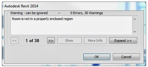
Here is a screenshot of the first error message that was ignored after a user changed a parameter to a level.


A few days later another user notices that a series of rooms are no longer enclosed, when their screen looked like this:


Below is the process that is required to determine what happened and why the rooms were no longer enclosed:

  • Are all the rooms not enclosed or just a few? To check this, take a look at a few of the wall properties in the surrounding rooms and make sure the Room Bounding parameter is checked.  
Room Bounding Checked - Not the Issue Here


  • Is this happening on just this floor or on other floors as well?  To verify, check the base offset, limit offset and upper offset values.
Values are correct - Not the Issue
  • Next step is to check the properties of the level that the rooms are hosted on.  The first step is to check the computation height of the level.
  • When the computation height overlaps another floor with rooms, you will see the following warning message:
DO NOT IGNORE THIS ERROR MESSAGE
  • When the computation height overlaps bounding objects (like walls that are room bounding), you will see the following warning message:
The computation height relates to room bounding objects that are hosted to that level.
  • So, what happened?  How did the computation height at the level change to 100' above the level?  In a section view, a user wanted to show the actual elevation (survey point), rather than the project level, to tie the building into the Civil drawings for a project.  Instead of using a Project Base Point or a Survey Point reference, they chose to change the computation height.  When they did this, they ignored the error message and did nothing.  There was no visible change to the elevation level, so they moved on.

The Moral of the Story:
Our BIM team often tells users that the can ignore certain error messages, like walls overlapping room separation lines and objects slightly off axis.  In general, this is not the best practice, as all warning messages are really warning you that you might be, most likely are, doing something wrong.  Many warning messages are precursors to model performance issues or worse; model corruption.

Moving forward, please do yourself and your teams a favor and start reading your warning messages.  If you don't understand the error or are unsure what to do to correct it, share your message with your Project BIM Coordinator, or if you do not have one, a member of the BIM Standards Team.  

Corrections to complicated errors, like the one indicating above, can take hours or days to troubleshoot and preventing them is the best course of action.


Preventing Accidental Clicks

Preventing Accidental Clicks


Have you ever tried to click on a door but accidentally double clicked on the door tag instead?  When you double click on a family, you are immediately brought to the family file for editing.  Did you know that you can configure your settings to avoid this?  Simply follow the steps below:

  • Click on the Revit Symbol (R:) and select options.
  • Once inside the options menu, select the user interface tab.
  • Click on the customize option next to Double-click Options and change the family option to Do Nothing.


Keyboard Shortcuts

Keyboard Shortcuts


Did you know that you can customize your keyboard shortcuts by adding new commands to increase speed and efficiency?

In Revit 2014, viewports can now be activated by double-clicking on the viewports on your sheet, but there is no fast way to deactivate them.  However, by customizing our shortcuts we can create one to eliminate the need to right click and select the deactivate option.

To add a keyboard shortcut use the following steps:

  • Type KS to access the shortcut preferences.

  • In the search bar, type dea to filter to available commands down to only Viewports:Deactivate View.
  • Click on the Viewports:Deactivate View command.  This will activate the Press new keys option.
  • Type the shortcut you would like to use.  I recommend XX as it is close to where our hands usually are, but you can use whatever you prefer.
  • Click the Assign button.
  • Click OK to close out of the window.

Cut Profile Tool

Changing the Cut Profile of Elements

    When creating enlarged plan or sectional details, the out-of-the box REVIT view rarely displays to properly displays what the built construction will be.  To modify this, we should use the Cut Profile tool.  This keeps the modeled assembly visible in our details in the event that a wall moves or is otherwise altered.  We SHOULD NOT hide the model and use a filled region to adjust our details.
    We can use the Cut Profile tool to change the shape of elements that are cut in a view, such as roofs, floors, walls, and the layers of compound structures. The tool is available in plan, RCP, and section views. Changes made to the profile are view-specific; that is, the element's 3D geometry and its appearance in other views does not change.
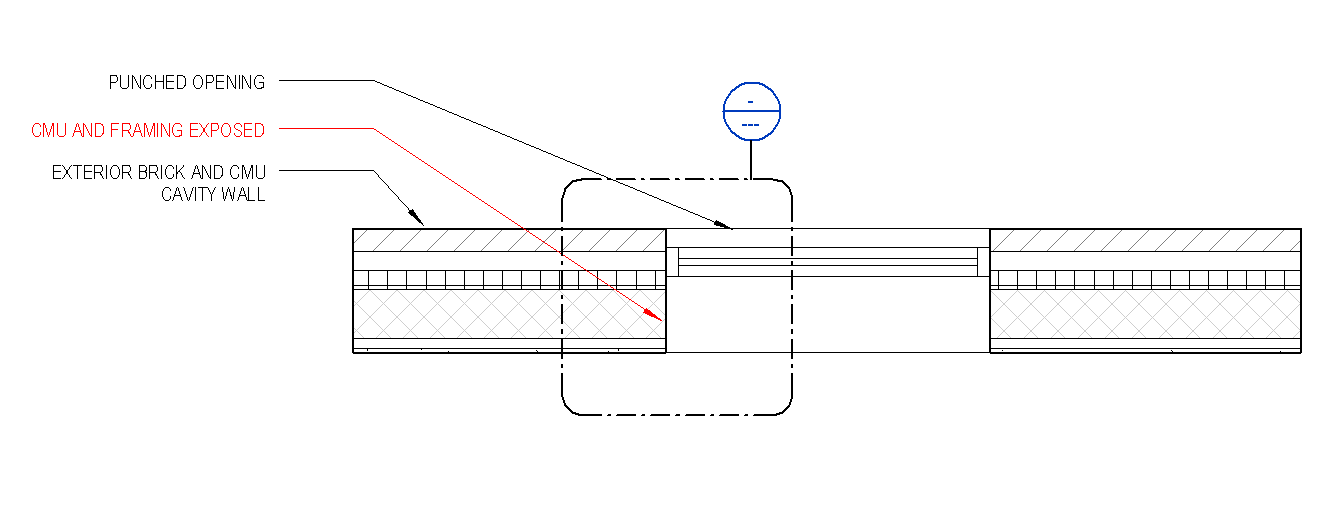
    Let's start with a basic exterior brick on CMU cavity wall assembly with a window placed somewhere along the wall.


    Once we have this created, we can create an enlarged jamb detail.  As you can see, by default the wall construction is cut at the location of the window, despite the fact that in the wall properties we have indicated for the interior to wrap at inserts.
    To adjust the jamb detail, we will use the Cut Profile Tool, located under the view tab in the ribbon.


    Once inside the Cut Profile tool, we must select a cut face (layer of the wall, ceiling, etc.) to modify the boundary.  It is important to note that the Cut Profile tool allows you to modify each layer of the wall assembly (gypsum board, metal stud, CMU, etc.) independently from one another, allowing one element to return and others to extend.  The first surface we will extend will be the gypsum board to return it to the window mullion.  If we click on the gypsum board, we will enter a sketch mode with the existing boundary shown with orange lines.  Once in the sketch mode, draw lines to indicate the extents of the modification you would like to make, indicated with purple lines.  The third component is a purple arrow.  The arrow must point to the side that you want to keep (see the image below).
    After the sketch is completed, click the green check mark to finish the modification.
    Repeat these steps for all items that you wish to cut and add detail components as necessary to complete the detail.