Creating Project Key Plans
For the vast majority of projects that we work on, from a small tenant fit-out to a large new educational building, a Key Plan is an important piece of information included within our title-block to orient the Contractor.
There are two methods for creating and showing key plans that are to be utilized as outlined below.
Key Plan Option #1 - Within the Title Block Family
For the majority of our projects, a key plan within the title-block is the recommended method. For this method to be feasible the following must be met.
Key Plan Option #2 - As a Legend
For a small number of our projects, the key plan can not be the same on all sheets. The most common example of this is a building whose footprint is so big that the floor plans do not fit onto a single sheet and are subdivided into multiple sheets using match lines. Another example would be a project with both renovation work and some for of an addition. This would require a key plan for the demolition plans, showing the existing building only, and a key plan for the addition, showing both the existing building and the new addition.
This method is currently being used on our project at HCC, as we have both a building footprint that does not fit onto a single sheet and a scope of work that includes both renovation and an addition. Below is a view of our project browser, with the series of key plan legends that are currently utilized on the project. As you can see, we currently utilizing 10 key plans. The most common are the Demo and Construction plan legends. The addition for this project has varying floor plate sizes, so additional key plans have been created for the 1st, 2nd and 3rd floors of the addition.
There are two methods for creating and showing key plans that are to be utilized as outlined below.
Key Plan Option #1 - Within the Title Block Family
For the majority of our projects, a key plan within the title-block is the recommended method. For this method to be feasible the following must be met.
- The plans (floor, ceiling, demo, roof, etc.) being shown on the plans are always the same. The best example of this is a tenant fit-out project. The location of a tenant space within the larger floor plate of a building is consistent and can be used on all sheets.
Once it is determined that the above criteria is met, the actual key plan can be created. To create the key plan for the project, the following steps should be taken:
- Select the Amenta/Emma Standard title-block loaded into your model from the starting template. The title-block will turn blue, indicating it has been selected. On the ribbon, click the Edit Family Icon to enter the family editor.
- Once inside the family editor, zoom into the area of the title-block reserved for the key plan. The key plan can be created one of two ways, either by importing an image that has been previously created for the project, or by creating a series of lines and filled regions for the project.
- Assuming an image has already been created, browse to the insert tab and select image. Select the image and load it into the project. Place it on the sheet and scale the image accordingly to fit the key plan area. After the image has been set, adjust the North arrow to represent true orientation, including a Project North, if applicable.
- If an image has not been created, draw the key plan using lines and filled regions. Adjust the North arrow as indicated above.
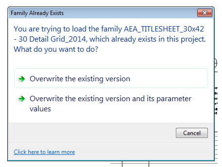
- Once the image has been loaded, or the plan drawn, save your title block family in your project folder and load it into your project and select the Overwrite the existing version and its parameter values option. This will update all sheets in your project using this title block.
Key Plan Option #2 - As a Legend
For a small number of our projects, the key plan can not be the same on all sheets. The most common example of this is a building whose footprint is so big that the floor plans do not fit onto a single sheet and are subdivided into multiple sheets using match lines. Another example would be a project with both renovation work and some for of an addition. This would require a key plan for the demolition plans, showing the existing building only, and a key plan for the addition, showing both the existing building and the new addition.
This method is currently being used on our project at HCC, as we have both a building footprint that does not fit onto a single sheet and a scope of work that includes both renovation and an addition. Below is a view of our project browser, with the series of key plan legends that are currently utilized on the project. As you can see, we currently utilizing 10 key plans. The most common are the Demo and Construction plan legends. The addition for this project has varying floor plate sizes, so additional key plans have been created for the 1st, 2nd and 3rd floors of the addition.
How to Create a Legend Key Plan
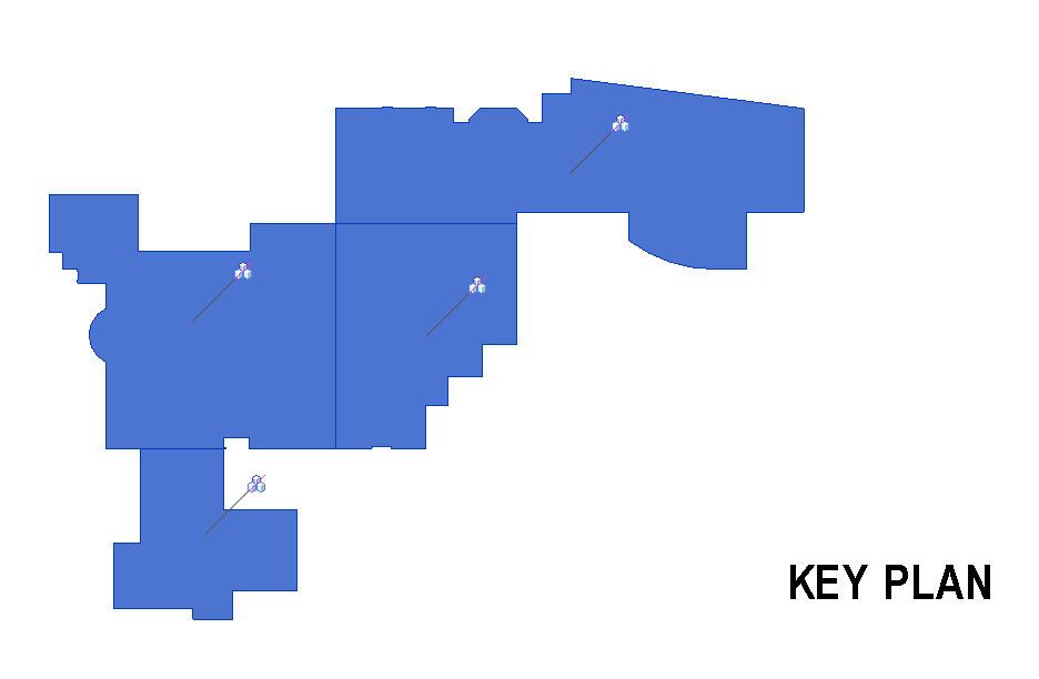
Once the building footprint has been established for the project, the simplest way to create a key plan is to draw a filled region around the perimeter of the building. Once this filled region has been created, we can create our key plan from that. Follow the steps below:
- Create a new legend from the View Tab -> Legends -> Legend.
- Go to the floor plan and copy the filled region that you created. Paste the filled region into your legend view.
- Change the scale to a small scale, something like 1" = 100', although actual scale will vary depending on the size of your building.
- Create filled regions for each wing of the building. In the case of HCC, we have 4 wings for the new work.
- In the first legend, change all but 1 wing to the pattern "Solid White". Change the active wing to "Existing Construction".
- Duplicate this legend as many times as necessary for your project, changing which wing is hatched. Place the legend on your sheet, in the key plan location for all projects that are non-state or client title-block driven. Make sure the correct key plan is placed on the corresponding plans.


No comments:
Post a Comment