Monday, July 25, 2016

Checking-out an AutoCAD License for Field Work

Checking-Out an AutoCAD License for Field Work


If you choose to complete your field verification with AutoCAD (as opposed to Revit), the following is the process for checking-out a license.

Open AutoCAD and click on the pull-down next to the question mark in the upper right hand corner.  


Click on About Autodesk AutoCAD 2017, which will bring up the About Dialog Box.  Click on the Manage License Button.


This will bring up the License Manager window.  Click on the Borrow Button.


A calendar will appear.  Select the day for which you need to borrow the license - Licenses should only be borrowed for 1 day at at time to avoid others from not having licenses available for working within the office.  Click on the date and hit the Borrow License button.


If done correctly, you will receive a message indicating that you have successfully borrowed a license and the scheduled return date.


Note that the license will return automatically at midnight on the day you have selected.

Monday, February 1, 2016

Understanding PAT Files

Understanding PAT Files


Filled regions are used on every Revit project that we do.  While our library has a large number of standard materials created as filled regions, a specific design may require a new filled region to be created.

Complex filled regions are created using PAT files.  If you are not familiar with PAT files, at first glance they can be somewhat confusing.  The below is a summary of what each number in the pat file means, so you can be better equipped to create your own custom PAT files for your projects.  

First, the default Revit .pat file is located here:  C:\Program Files\Autodesk\Revit Architecture 2016\Data.  When making new patterns files, I often find the best way to do it is to start a new notepad file for your specific filled region.  If you think your filled region should be incorporated into the office template file, please e-mail it to me and I will take a look and include in the next template update.

Here in an example of a new .pat file that was created for a project in the office last week, for a 24 x 36 cork wall tile, in a running bond pattern.

And now for the notepad file that was used to create this pattern.

*Cork Tile 36x24, 36 x 24 Tiles Stagger
;%TYPE=MODEL
0,     0,     0,      0,      24
90,   0,     0,     24,     18,     24,     -24

The first row of numbers creates the horizontal lines for the pattern:
Angle            = 0         -->  lines are horizontal
x,y origin       = 0, 0    -->   defines the starting point of the lines
shift               = 0        -->  line pattern is not shifted
offset            = 0         -->  consecutive lines are 24 inches apart
no line pattern            -->  the line is solid

The second row of numbers creates the vertical lines for the pattern:
Angle            = 90      -->  lines are vertical
x,y origin       = 0, 0    -->  pattern begins at the same point as the horizontals
shift               = 24      -->  line pattern is shifted by 24 model units for consecutive lines
offset            = 18       -->  consecutive lines are 18 inches apart
dash             = 24       -->  each line is built of 24" dashes and 24" spaces
space           =24        -->  this pattern repeats until the face boundary


Sunday, June 21, 2015

Finish Plans with Dynamo

Finish Plans with Dynamo


One of the most time consuming pieces of defining the finishes within our Construction Documents is filling in the finish tag for each room.  Under the current method, you must either edit the tag on a room by room basis, update in the room properties or update in a room schedule.  While each of these are valid methods, they are time consuming based on the functionality of Revit.

Fig-1:  A|E Standard Finish Tag (note the new order of finishes to follow a top to bottom progression)


Using a custom Dynamo script, we can now fill out our finish tags in plan via Excel.  The following is the process (assuming you already have installed Dynamo).

  • Open your Finish Floor Plan and place your room tags in each of your rooms.  This task is still time consuming in Revit 2015.  (Sneak preview, this will be enhanced in the new 2016 version.
Fig-2:  Sample Floor Plan with Finish Tags Added
  • Now that your finish tags are placed, we can launch Dynamo via the add-in tab in Revit.  (Note:  Finishes can be entered prior to placing the finish tags if desired).
Fig-3:  Dynamo Add-In
  • Once clicked on, Dynamo will launch in a new window and you will be brought to the Dynamo splash screen.  From here, we will be able to use the Open command to load our custom script. 
Fig-4:  Dynamo Splash Screen
  •  Click on the open command and browse to our library and the Dynamo folder.  The script we are utilizing today is named "Room Data Exporter.dyn".  This will open the script for us to use.
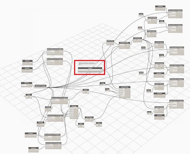
Fig-5:  Full View of Dynamo Script
  • Once you have opened the script, focus your attention on the Browse node near the center of the screen (see red image above).  This is the only modification that a user needs to complete to use this script.  This Browse node needs to point to the location of your excel file.  Note:  You will need to create a blank Excel file within your project folder structure.  Once you select your file, the file path will be inserted below the Browse button (see Fig-6 below).
Fig-6:  Enlarged View of Browse Node
  • Once you have pointed the script to your excel file, Click the Run button in the lower left hand corner.
Fig-7:  Run Button to activate the script
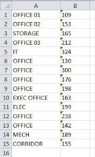
  • After pressing the Run button, Excel will open and extract the Room Names and Room Numbers from your Revit File (see Fig-8).  Note:  After pressing run, you will see yellow text appear to the right of the Run button indicating "Run completed with warnings".  This is normal and will appear until all of the finishes have been filled out for ALL of your rooms, not just the rooms on your sheet.  This will also serve as a good way to check if you have rooms in your model that are not placed and possibly left over from earlier phases, designs, etc.
Fig-8:  Excel Initial Creation
  • Once the initial excel file has been generated, you now will start to input the desired finishes into the excel file, so that they can be pushed back into Revit.  Your data will be input into columns C, D, E and F.  The order of the finishes follows the finish tag.  Column C = Ceiling Finish, Column D = Wall Finish, Column E = Base Finish, Column F = Floor Finish.  Once you have entered your finishes into Excel, save your Excel file.
Fig-9:  Completed Excel File
  • After saving, go back into Dynamo and click Run again and the finishes will populate into your Revit finish plans.
Fig-10:  Complete Finish Tags via Dynamo
Fig-11:  Completed Exec Office Tag in Revit

Fig-12:  Corresponding Finish Information in Excel
Once the data is pushed back into Revit, you have the option of either editing within Revit individually, or re-running the Dynamo script and editing in Excel.  Hopefully this will help speed up the process of entering finishes into our Documents.

Friday, June 5, 2015

QUICK TIP - COMPONENT PLACEMENT

Quick Tip - Component Drop Down


Searching for a family to place into your model or detail that is loaded into the project and you don't want to scroll through the entire list or use the browser on the bottom left?

In 2015, you are in luck!  You can now search the component drop down list by typing the name of the family, or the specification number if you are using the new family naming conventions.

Looking for a CMU detail component?  Simply start to type 04 and the list is filtered with your search criteria highlighted in yellow.

Wednesday, May 20, 2015

Snap Override

Quick Tip - Snap Override


Whether you are sketching the outline of a model element (roof, floor, etc.) or trying to draw a detail line, it is inevitable that at some point you will encounter a situation where Revit does not let you draw the line at the angle you want (typically less than 2 degrees).  This can become very frustrating for many users.


Luckily, if you remember your days in AutoCAD (I know, I used the word AutoCAD in a Revit post), you can use a tool very similar to manual snap override in Revit and it is SIMPLE to  use.  Simply follow these steps:


  • Sketch your line as you normally would.
  • When you are unable to connect your line as you want to, Right Click in your space and click on the Snap Override text.  This will bring up a list of available snaps that you can select from (See Fig-1 below).  Click the snap you want and now you will only select that type of snap.

Fig-1:  Snap Overrides

This can also save you time if you are used to using your "TAB" key to cycle through all of your snap options.  Now, you can isolate the type of snap you are looking for.


Friday, May 15, 2015

Using the Toilet Partition Family

Railings - Instance Modification


The goal of this post is to walk you through how to use the toilet partition families that are standard within our library, as requested at a previous BIM Stand Up Meeting.

The first step would be to identify the correct family to use.  When browsing to folder 102113.17 Phenolic Core Toilet Compartments, you will notice 3 separate folders, indicating the 3 different configurations (Fig-1).

Fig-1:  Library Folders

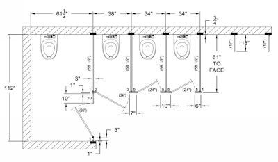
Here is a graphic representation of the 3 different configurations (Fig-2, 3 and 4).

Fig-2:  Straight Run - No ADA
Fig-3:  Alcove ADA + Standard
Fig-4:  Straight Run ADA + Standard

Once you have identified the correct family to use and have loaded it into your file, you will notice a wide assortment of parameters within each family.  The following construction parameters can be controlled:
  • Right Panel:  When checked, a panel will be visible at the rightmost end partition.  When unselected, no panel is visible and allows for a wall at the end.
  • Left Panel:  Same as Right Panel only on left hand side.
  • Standard Stalls:  Changes the number of standard stalls in a given layout.  The number includes an ambulatory stall when the AMB Stall parameter is selected (see below).
  • Continuous Brackets:  When checked, full height continuous brackets appear in the family model.  When not checked, standard stirrup type brackets appear.
  • AMB Stall:  When checked, a 36" clear ambulatory stall with an out-swing door appears adjacent to the ADA stall.  When not checked, a standard stall is utilized.
  • Outswing Door ADA:  When selected, the alcove ADA door will swing outward.  When not selected, the door swings inward.
  • Door Opening Angle:  Allows for revision of the door swing angle in the 3D elements.  All doors within the family will update.  This should be left at 0 degrees for a closed door.
  • Outswing Door:  When selected, the standard doors will swing outward.  When not selected, the door(s) swing inward.  Inward swing is standard.
In addition to the construction parameters, the dimension parameters may be adjusted to facilitate specific sizes.  Stall width, depth and door width parameter values may all be adjusted.

Below is an example including a plan and the parameters used to obtain the plan.
Fig-5:  Alcove ADA + Ambulatory + 2 Standard Stall Sample

Fig-6:  Parameters for fig-5
The other families will work in a similar fashion.  Additional examples can be found in the library folder labeled README.

Once you have gotten the toilet partition loaded in, you are ready to begin adding fixtures and accessories from our library under folder 102800 - Toilet, Bath and Laundry Accessories.

Friday, May 8, 2015

Railings - Instance Modifications

Railings - Instance Modification


The previous post was intended to familiarize you modifying railings and handrail types at the Type level.  In this post, we will go through how to modify railing components at the instance level.  

  • Hover over the railing of which you wish to make instanced based edits.  For this example, we will look at duplicating a support bracket on a wall mounted handrail.  Refer to Fig-1 for an elevation view of a wall mounted handrail with standard spacing as driven by our Handrail Type, prior to instance based editing.
Fig-1:  Elevation View Type Driven Support Spacing

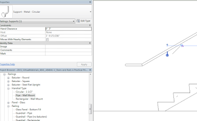
  • While hovering over the Railing Type, hit Tab to cycle through your selection options until you can select only the support bracket closest to the bottom of the stair run.  The support bracket will be selected and a pin icon will appear (Fig-2).  This is telling us that the position of this support bracket is driven by the Type Properties of the Handrail Type.  Also note that the properties of the support bracket, including the preview image, are grayed out (Fig-3).
Fig-2:  Support Bracket Selected

Fig-3:  Support Bracket Pinned
  • If we wish to move the bracket or modify the support depth, click on the pin to allow instance based editing.  This will change the pin graphics to open as well as remove the grayed out tone from the Properties dialog box.
Fig-4:  Support Bracket Unpinned
  • Once the support is unpinned, you are now able to edit the individual support on an instance basis.  Changes made to this support, be-it location, hand clearance, etc. will only apply to this one support bracket.  Brackets can be moved by entering a horizontal distance and the support will automatically move to remain attached to the rail.  If you move a support by mistake, clicking the pin will return the object to its original Type driven location.
  • If you wish to copy a support, you do not need to unpin the original object.  Simply use your copy command and add a bracket at the desired location.  The newly copied support will be automatically unpinned because it not driven by the Type Properties of the Handrail Type (Fig-5).
Fig-5:  Copied Support vs Type Driven Support

  • It is important to note that only Continuous Rails, top rails as defined by a Top Rail Type and handrails as defined by a Handrail Type, and their sub-elements, supports and terminations, can edited on an instance level.  Non-Continuous rails do not offer this ability.
  • To edit that handrail itself, hover over the Railing Type and hit "Tab" until the handrail only is selected. Once selected, the new panel will appear in the Ribbon, labeled "Continuous Rail" (Fig-6).  By clicking on the Edit Rail button, we will be able to edit the handrail at the instance level.
Fig-7:  Continuous Rail Panel
  • Within the edit rail command, we are able to edit the profile as well as the path of the railing, by clicking on the Edit Path button (Fig-8).
Fig-8:  Edit Path
  • In addition to being able to edit the path of the rail from this dialog box, we also are given the option of editing the rail joins.  Once clicked, we will snap only to intersections of rail segments.  Once selected, the adjacent combo box will become activated and we can modify the join from by type to either Miter or Fillet.  If we chose fillet, we must specify a radius for the join.  A miter and fillet join are indicated below in Fig-9.1 and 9.2.
Fig-9.1:  Mitered Rail Joint
Fig-9.2:  Fillet Rail Joint


  • Once you are happy with your edits, click the green check mark twice to complete your edits.
  • Feel free to experiment with your railing edits on an instance level.  You always have the ability to go back to the Type driven properties by selecting the Railing Type and hitting the Reset Railing button (Fig-10).
Fig-10:  Reset Railing